
栅极驱动器
采用罗姆独创的微细加工技术,开发出片上变压器工艺。进而成功开发出小型、内置绝缘元件的栅极驱动器。
轻松搜索
| Power Device | Isolation Voltage | Driving Capability(Iout) | Function | Operation Voltage | Secondary side | Miller Clamp | Secondary UVLO [ON/OFF] | Short Circuit Protection (Note 2) |
DESAT (Note 2) | Soft Turn OFF after short detection |
Temp Monitor | Thermal shut down with Ext. Sensor |
Package | Evaluation Kit | ||
|---|---|---|---|---|---|---|---|---|---|---|---|---|---|---|---|---|
| Simple | Complex | Positive Voltage | Negative Voltage | |||||||||||||
| Automotive | ||||||||||||||||
| ~Gen3 SiC Drive voltage over 18V |
3.75k Vrms |
±4A | BM61S40RFV-C | - | 4.5 to 5.5V |
16 to 20V |
- | Built-in | 14.5V/ 15.0V |
- | - | - | - | - | SSOP-B10W | ✔ |
| BM61S41RFV-C | 16 to 24V |
- | Built-in | 14.5V/ 15.0V |
- | - | - | - | - | SSOP-B10W | ✔ | |||||
| SiC, IGBT, Si-MOSFET |
3.75k Vrms |
±20A | - | BM6112FV-C | 4.5 to 5.5V |
14 to 20V |
-12 to 0V |
Ext. MOSFET | 11.5V/ 12.5V |
✔ | ✔ | ✔ | ✔ | - | SSOP-B28W | - |
| 2.5k Vrms |
±9A | - | BM60060FV-C | 8 to 24V |
13.5 to 24V |
- | Built-in | 11.5V/ 12.5V |
✔ | - | ✔ | ✔ | - | SSOP-B28W | - | |
| ±5A | - | BM60055FV-C | 4.5 to 30V |
9 to 24V |
- | Built-in | ✔ (Note 1) |
✔ | - | ✔ | - | ✔ | SSOP-B28W | - | ||
| ±4.5A | - | BM6109FV-C | 4.5 to 5.5V |
14 to 18V |
- | Ext. MOSFET |
12.0V/ 12.5V |
✔ | - | ✔ | ✔ | - | SSOP-B28W | - | ||
| ±3A | - | BM6101FV-C | 4.5 to 5.5V |
14 to 24V |
-12 to 0V |
Ext. MOSFET |
11.5V/ 12.5V |
✔ | ✔ | ✔ | - | ✔ | SSOP-B20W | - | ||
| BM6102FV-C | 4.5 to 5.5V |
14 to 20V |
- | Ext. MOSFET |
11.5V/ 12.5V |
✔ | ✔ | ✔ | - | ✔ | SSOP-B20W | - | ||||
| BM6104FV-C | 4.5 to 5.5V |
10 to 24V |
-12 to 0V |
Ext. MOSFET |
9.05V/ 9.55V |
✔ | ✔ | ✔ | - | - | SSOP-B20W | - | ||||
| BM60052AFV-C | 4 to 32V |
10 to 20V |
-12 to 0V |
Built-in | ✔ (Note 1) |
- | ✔ | ✔ | - | ✔ | SSOP-B28W | - | ||||
| BM60054AFV-C | 4 to 32V |
10 to 20V |
-12 to 0V |
Built-in | ✔ (Note 1) |
✔ | ✔ | ✔ | - | ✔ | SSOP-B28W | - | ||||
| Si-MOSFET | 3.75k Vrms |
±4A | BM61M41RFV-C | - | 4.5 to 5.5V |
9 to 24V |
- | Built-in | 7.4V/ 7.8V |
- | - | - | - | - | SSOP-B10W | ✔ |
| Industry | ||||||||||||||||
| SiC IGBT Si-MOSFET |
2.5k Vrms |
±3A | - | BM6108FV-LB | 4.5 to 5.5V |
10 to 24V |
-12V to 0V |
Ext. MOSFET |
9.05V/ 9.55V |
✔ | ✔ | ✔ | - | - | SSOP-B20W | - |
| Si-MOSFET | - | +3.5A/ -4.5A |
- | BD2320UEFJ-LA | 7.5 to 14.5V |
- | - | - | - | - | - | - | - | - | HTSOP-J8 | - |
| GaN HEMT | - | +7A/ -5A |
BD2311NVX-LB | - | 4.5 to 5.5V |
- | - | - | - | - | - | - | - | - | SSON06RX2020 | ✔ |
| Consumer | ||||||||||||||||
| Si-MOSFET | - | ±4A | BD2310G | - | 4.5 to 18V |
- | - | - | - | - | - | - | - | - | SSOP5 | - |
(Note 1) OFF/ON Voltage is adjustable by external settings
(Note 2) Either of SCP and DESAT function can be used
参数搜索


Matching Parts: 25 | ?供应情况 | Grade | Isolation Voltage [Vrms] | Channel | Vcc1 (Min.) [V] | Vcc1 (Max.) [V] | Vcc2 (Min.) [V] | Vcc2 (Max.) [V] | VEE2 [V] | Iout [A] | I/O Delay Time (Max.)[ns] | Min. Input Pulse Width [ns] | Temperature (Min.)[°C] | Temperature (Max.)[°C] | Switching Controller | Temperature Monitor | Package | Functional Safety | Common Standard | ROHM Solution Simulator | EVK Information |
|---|

评估板
为了确保功率器件能够安全且充分发挥性能地工作,栅极驱动器IC的选择十分重要。
ROHM的栅极驱动器IC评估板具有以下产品阵容。
考虑到栅极驱动器IC评估板需要连接到设置板上的功率器件以进行评估,所以减小了基板面积。
单通道栅极驱动器IC的评估板除了有1pcs实装品之外,还提供适用于板桥电路的2pcs实装品。
此外 ,通过启用栅极驱动器IC用的Spice模型,还可以通过Simulation进行应用验证。
使用案例
开发板上栅极驱动器IC的替换案例

栅极驱动器IC评估板可用于替换开发板上的栅极驱动器IC。
不同封装和引脚的栅极驱动器IC很难在开发板上进行直接替换。
栅极驱动器IC评估板的电源、信号输入输出端子的布局考虑到与开发板的布线链接,也可在评估板上使用需要调整的栅极电阻。
Galvanic Isolation Series [Isolation Voltage: 3.75kVrms]
| 评估板 | 栅极驱动器IC | 评估板 | ||||||||
|---|---|---|---|---|---|---|---|---|---|---|
| EVK Name | Application | Gate Drive Voltage, Current |
Gate Drive Channel |
电路板 概要 |
Board size [mm] |
Parts Name | IC概要 | Spice 模型 |
评估板 使用指南 |
购买 |
| BM61S40RFV-EVK001 | SiC MOSFET Gate Drive |
16 to 20V, 4A (Note 1) |
1ch | 概要 | 33 x 16 | BM61S40RFV-C |  概要 |
Spice 模型 |
使用指南 | 网上代理店 |
| BM61S40RFV-EVK002 | 2ch | 33 x 32 | 使用指南 | 网上代理店 | ||||||
| BM61S41RFV-EVK001 | SiC MOSFET Gate Drive |
16 to 24V, 4A |
1ch | 33 x 16 | BM61S41RFV-C | Spice 模型 |
使用指南 | 网上代理店 | ||
| BM61S41RFV-EVK002 | 2ch | 33 x 32 | 使用指南 | 网上代理店 | ||||||
| BM61M41RFV-EVK001 | Si MOSFET Gate Drive |
9 to 24V, 4A |
1ch | 33 x 16 | BM61M41RFV-C | Spice 模型 |
使用指南 | 网上代理店 | ||
| BM61M41RFV-EVK002 | 2ch | 33 x 32 | 使用指南 | 网上代理店 | ||||||
(Note 1) Max Gate Drive Voltage is protected by Over Voltage Protection
评估板
Galvanic Isolation Series在对应基础绝缘的应用方面拥有单通道驱动产品,以及可以应用在板桥电路上的双通道驱动产品。
1ch Galvanic Isolation Gate Driver Board (1pcs)
使用指南
相关产品
2ch Galvanic Isolation Gate Driver Board (2pcs)
使用指南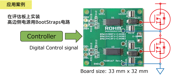
相关产品
栅极驱动器IC
Small footprint for 8mm creepage distance

- 1ch栅极驱动器
- Small Package: 3.5mm x 10.2mm x 1.9mm
- 基础绝缘
- Miller Clamp 内置电路
- I/O Delay time: 65ns (Max)
- 通过双输入信号(INA、INB)实现伴有输出逻辑控制、外部噪音的栅极“H”输出防止设计
- 输入信号电压(Note 2): VINH:2.0 V or over / VINL : 0.8V or under
(Note 2) 信号输入侧的电源电压范围(VCC1)是与输入信号无关的4.5~5.5V。
Truth table
| INA (input) |
INB (input) |
OUT (Output) |
|---|---|---|
| L | H | L |
| H | L | H |
| L | L | L |
| H | H | L |

1200V High Voltage High and Low Side Driver
| 评估板 | 栅极驱动器IC | 评估板 | ||||||||
|---|---|---|---|---|---|---|---|---|---|---|
| EVK Name | Application | Gate Drive Voltage, Current |
Miller Clamp | 电路板 概要 |
Board size [mm] |
Parts Name | IC概要 | Spice 模型 |
评估板 使用指南 |
购买 |
| BM60212FV-EVK001 | IGBT Gate Drive Si MOSFET Gate Drive |
10 to 24V, 3A (Note 3) |
Built-in | 概要 | 33 x 21 | BM60212FV-C |  概要 |
- | 使用指南 | 网上 代理店 |
| BM60213FV-EVK001 | - | BM60213FV-C | - | 使用指南 | 网上 代理店 |
|||||
(Note 3) Power supply voltage is from 10 to 24V relative to low-side and input-side ground.
评估板
仅需与应用链接,即可简单替换。
使用指南
栅极驱动器IC

- Turn on/off time: 75ns (Max)
- 通过三输入信号(EN、INA、INB)实现输出逻辑控制。通过外部噪音实现高侧、低侧同时ON防止设计
- Package: 6.50mm x 8.10mm x 2.01mm
- Miller Clamp内置电路 [仅BM60212FV-C]
- 输入信号电压(Note 4): VINH : 2.0 V or over / VINL : 0.8V or under
- Gate Drive Voltage:10 to 24V
- Gate Drive Current:3A
(Note 4) 电源电压范围(VCCB)10~24V。
Truth table
| ENA (input) |
INA (input) |
INB (input) |
OUTA (output) |
OUTB (output) |
|---|---|---|---|---|
| L | X | X | L | L |
| H | L | L | L | L |
| H | L | H | L | H |
| H | H | L | H | L |
| H | H | H | L | L |

Power Device Lineup

